en:pfw:reflection-sensors
Table of Contents
Reflection sensors
Idea
A reflection sensor is most of the time a sensor that uses (infrared) light to detect the precence of an object.
TCND5000 the demonstrated sensor
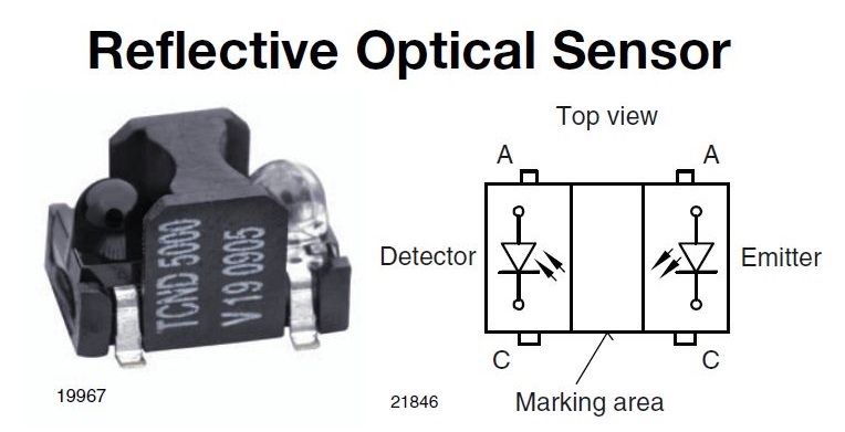
Upper left: The TNCD5000 is a sensitive photo diode and an infrared led in one case.
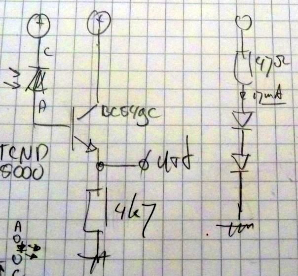
Upper right: A sketch of the TCND5000 driver.
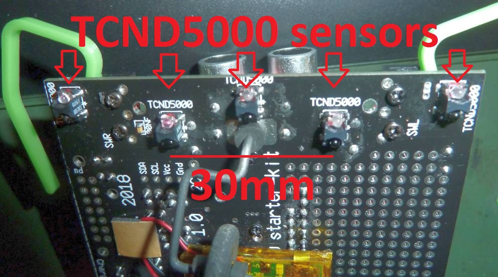
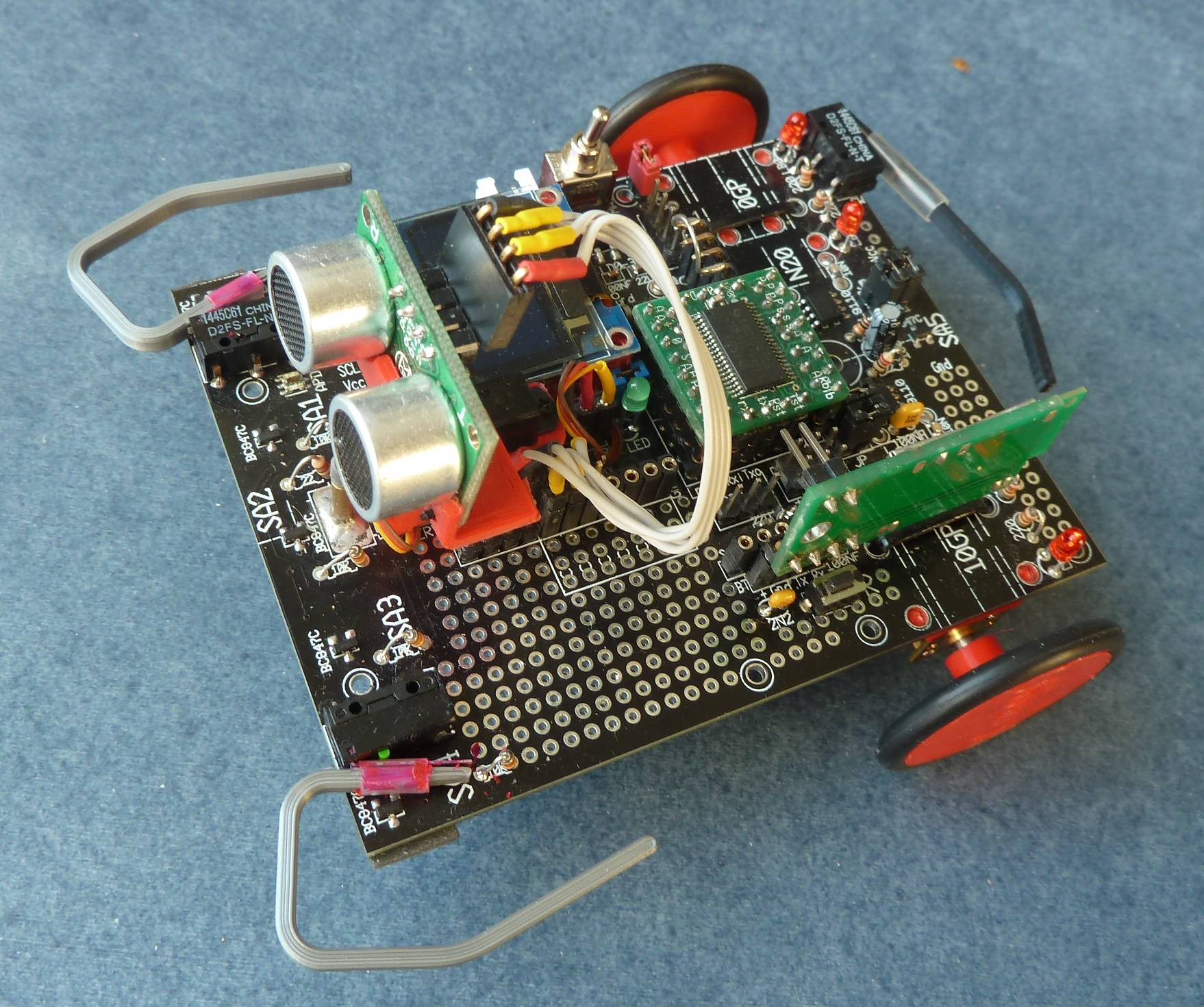
Lower left: Five sensors mounted on Cosey's PCB.
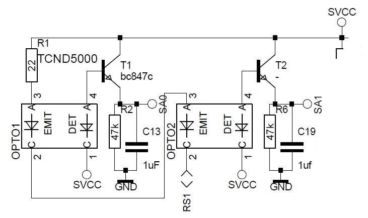
Lower Right: Piece of schematics of the Cosey robot, note that the resistor values have changed!
Pseudo code
Function: REFLECTION  ( adc -- +n )
  Read adc input 'adc' leave the reading '+n'

Function: FLOOR  ( adc -- +s )
  Read adc input 'adc' and leave the scaled result '+s'

Function: RAVINE  ( -- 0|1|2|3 )
  Read the three adc inputs from the front of a robot.
  Translate the results to the numbers 0 to 3, indicating
  which sensor(s) where fired. Zero means non.

Function: BACKWARD?  ( -- flag )
  Test the sensor on the backside of a robot, leave true
  if the sensor is fired, otherwise false
Generic Forth
\ Reflection sensor example as used with the Cosey robot
\
\ Each sensor output is connected to an ADC input with 12-bit resolution
\
\ Words with hardware dependencies:
\ : **BIS       ( mask addr -- )      tuck @ or  swap ! ;
\ : **BIC       ( mask addr -- )      >r  invert  r@ @ and  r> ! ;
\ : BIT**       ( mask addr -- 0|b )  @ and ;
\
\ Needed an ADC routine like this one for the MSP430FR5949:
\
\ We need to clear the ENC bit before setting a new input channel
\ ADC can be used with VCC and VREF (2.5V) as reference voltage
\ : ADC         ( adc fl -- +n )
\    02 800 **bic               \ ADC12CTL0  Clear ENC
\    100 and >r                 \ Use VREF when fl is true
\    1F and  r> or 820 !        \ ADC12MCTL0 Select input
\    03 800 **bis               \ ADC12CTL0  Set ENC & ADC12SC
\    begin 1 802 bit** 0= until \ ADC12CTL1  ADC12 busy?
\    860 @ ;                    \ ADC12MEM0  Read result
\
\ Activate an output on a PCA9632 I2C led output driver
\ The routine /MS waits in steps of 0.1 milliseconds
\ It is used here to give the sensor time to settle
\ : >ON         ( b -- )        8 >pca  1 /ms ; \ b = 1, 4, 10 or 40

\ Read sensor level from input 'adc' using VCC as reference
: REFLECTION    ( adc -- +n )    0 adc ;

\ FLOOR sensor result is scaled and gives a number from 0 to 10
: FLOOR     (  adc -- s )       reflection  180 / ;


\ Examples (Cosey's advanced commands):

\ 0 = No ravine             Table edge detection
\ 1 = ravine at left
\ 2 = ravine in front
\ 3 = ravine at right
: RAVINE           ( -- 0|1|2|3 )
    01 >on  01 floor 5 < if  3 exit  then   \ Right sensor
    04 >on  02 floor 5 < if  2 exit  then   \ Middle sensor
    10 >on  05 floor 5 < if  1 exit  then   \ Left sensor
    0 ;         \ No floor sensor at all triggered

\ True if reflection sensor on the backside goes over the edge
: BACKWARD?         ( -- f )    10 >on  0E floor 5 < ;
More info look at specific implementations, if any.
en/pfw/reflection-sensors.txt · Last modified: 2023-09-04 18:18 by uho

